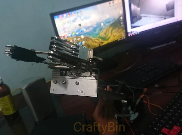
Arduino Controlled Robotic Arm with Servo Motors With Camera
The aim of this Project was to build a manually operated Robotic Arm with the grip.The project was completely successful. By building this project you may learn how to craft the right mechanisms for open/close positions of the arm grip among simple programming skills.
In this project an USB Camera is used for vision aid to determine the position of the gripper and to determine whether the object is gripped properly or not.The operation of camera is completely independent from robot arm operation and can be used externally.Using a USB camera is optional.Even without the camera, robot arm will work successfully.
Tools & Components
4 X Metal Gear Servo Motors(Tower Pro MG995)
4 X Potentiometers
1 X USB Camera Module(Optional)
5V Power Supply
Connecting Wires
3 X Aluminium Bars (Each 5cm long)
4 X H.D.D Actuator arms(Can be salvaged from old HDDs)
2 X H.D.D Platter with spindles
1 X Aluminium Plate(10cm X 5cm)
2 X Rubber sheet Pieces (4cm X 2cm)
Base( In here Metal box is used)
Nuts and Bolts
Drill
Screw/Flat Driver
Grip Piler
Connecting Circuit Components
Remember to Connect Power supply ground terminal to arduino ground terminal(Common Ground)Servos Must be supplied with 4.8V ~ 6V for best operation.
Servo 01 -Arduino Pin D6
Servo 02 -Arduino Pin D9
Servo 03 -Arduino Pin D10
Servo 04 -Arduino Pin D11
Potentiometer 01 - A0
Potentiometer 02 - A1
Potentiometer 03 - A2
Potentiometer 04 - A3
Building Robotic Arm
Servo motor 01 is used for Gripper mechanism
Servo motor 02 is used for Rotation of Gripper
Servo motor 03 is used for middle joint of two arms which connects Gripper & Base
Servo motor 04 is used for rotation of Base Plate
Crafted Robot arm is shown as below :
Arduino Code
//2020 CRAFTYBIN@Blogspot®
//Author - Chathura.H
#include <Servo.h>
Servo myservo1;
Servo myservo2;
Servo myservo3;
Servo myservo4;
int potpin1 = A0;
int potpin2 = A1;
int potpin3 = A2;
int potpin4 = A3;
int val1;
int val2;
int val3;
int val4;
void setup() {
myservo1.attach(6);
myservo2.attach(9);
myservo3.attach(10);
myservo4.attach(11);
}
void loop() {
val1 = analogRead(potpin1);
val1 = map(val1, 0, 1023, 0, 180);
myservo1.write(val1);
delay(15);
val2 = analogRead(potpin2);
val2 = map(val2, 0, 1023, 0, 180);
myservo2.write(val2);
delay(15);
val3 = analogRead(potpin3);
val3 = map(val3, 0, 1023, 0, 180);
myservo3.write(val3);
delay(15);
val4 = analogRead(potpin4);
val4 = map(val4, 0, 1023, 0, 180);
myservo4.write(val4);
delay(15);
}
//Upload the code and adjust the arm for different positions by controlling servos.
Further Development
You can use Raspberry Pi or similar platform with open CV to create a algorithm to detect and recognize specific objects using the camera.The robot arm can be programmed to function as a pick and place robot arm(Automated operation)
Using IR sensors or any object detection sensors, robot arm can be programmed to pick a specific object from other objects.(black & white)
Problems and Solutions
If any servo motor fails to operate and carry out its intended operation, that means the joint torque is more than the servo can handle.Try using a high torque metal gear servo motors(LD-20MG) for such joints.Don't use over-flexible aluminum bars for arm joints.
Base must be strong enough to hold the weight of entire robot arm.
Don't add unnecessary weights by using large washers,nuts or bolts-keep it simple and keep it light.
Otherwise it will affect the mechanism.
You can shape up the rubber pieces for better grip.
Did you make it ? Do you have any questions ? just ask!


Post a Comment